What Is a USB to HART Communication Module?

Time:2026-09-07 Author:Isabella
0%

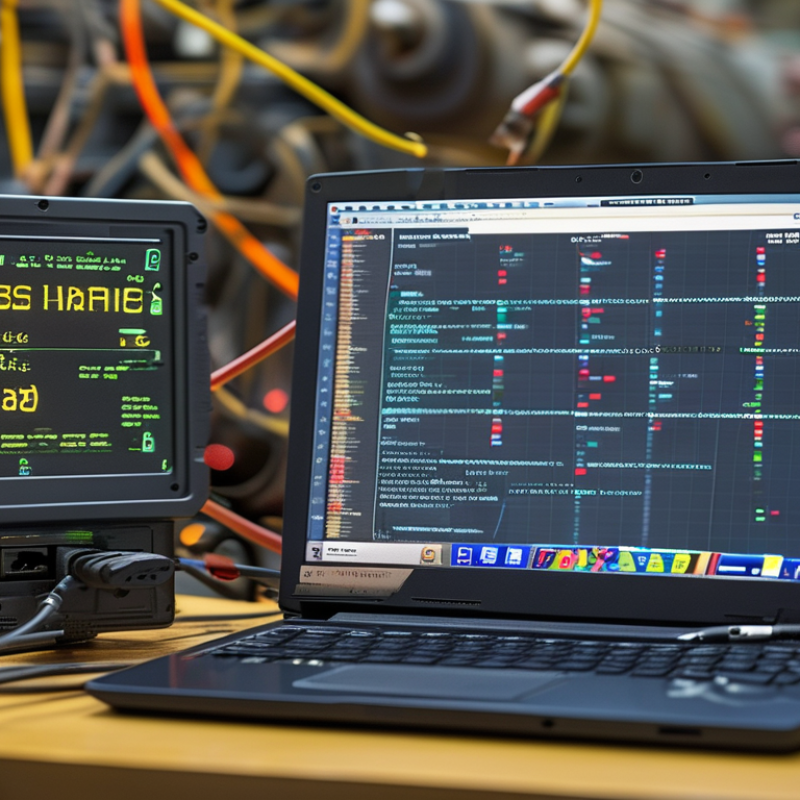
A Usb To Hart Communication Module connects a computer’s USB port with HART-enabled field instruments. It translates digital commands across the instrument’s existing 4–20 mA loop. Technicians can then read process values, configure parameters, and diagnose devices without replacing installed wiring. On a workbench, the setup may include a laptop, a loop power supply, two short leads, and one pressure transmitter. The practical benefit is immediate visibility. However, the module is not a complete control system. It still depends on correct loop resistance, stable power, compatible software, and proper device-description files.

FieldComm Group reports more than 40 million HART-enabled devices installed worldwide. Its HART Technology Overview describes HART as a global standard for digital communication over analog instrumentation wiring. ARC Advisory Group has also identified HART as a leading intelligent-device protocol in process automation. These figures explain the module’s continuing relevance in brownfield plants. As Ron Helson, former executive director of the HART Communication Foundation, stated, “HART technology is the global standard for sending and receiving digital information across analog wires.” That statement remains useful, although it should not encourage careless assumptions. A USB connection alone does not guarantee communication. Noise, incorrect resistance, or an unsupported device file can still interrupt a seemingly simple test. This article examines how a Usb To Hart Communication Module works, where it adds value, and what engineers should verify before trusting its readings. The details matter. Especially in older plants.

What Is a USB to HART Communication Module?

Definition and Purpose of a USB to HART Communication Module

A USB to HART communication module connects a computer with HART-enabled field instruments. It translates digital HART signals into data that software can read. HART communication usually travels over existing 4–20 mA wiring. This allows technicians to access device information without replacing the analog control signal.

The module supports tasks such as parameter configuration, measurement review, diagnostic checks, and device identification. A technician can connect it near a control cabinet or directly across the signal loop. The computer normally supplies the user interface, while the module handles signal conversion and communication timing. Some modules provide electrical isolation, which can reduce ground-loop risks. This feature matters in noisy industrial environments.

A USB connection seems simple. Wiring still deserves care. The loop may require suitable power and load conditions before communication works correctly. The module is not always a power supply for the field device. Correct drivers and compatible configuration software are also important. In practice, weak connections and incorrect loop resistance cause many failed tests. A field engineer should verify polarity, voltage, and safety procedures before connecting. I have found that software status messages can be misleading. A reported communication failure may come from wiring, not the module. That limitation deserves attention during troubleshooting.

What Is a USB to HART Communication Module? - Definition and Purpose of a USB to HART Communication Module

Data Dimension Technical Information Practical Purpose
Definition A USB to HART communication module is an interface that connects a computer or service device through USB to field instruments using the Highway Addressable Remote Transducer (HART) protocol. It enables a computer to communicate digitally with HART-capable field devices without requiring a dedicated internal communication card.
Communication Protocol HART uses frequency-shift keying (FSK) based on the Bell 202 standard. Digital data is transmitted at a nominal rate of 1,200 bits per second. It allows digital configuration and diagnostic information to be exchanged while preserving the conventional analog measurement signal.
Analog Signal Compatibility The digital HART signal is superimposed on a standard 4–20 mA process-current loop. The alternating digital component has an average value of zero, so it does not normally change the analog process variable. Existing 4–20 mA control and monitoring systems can often be accessed digitally without replacing the basic analog wiring.
Computer Connection The module communicates with the host computer through a USB port. The computer generally recognizes it as a serial or virtual communication interface after the appropriate driver is installed. USB provides a widely available connection for commissioning laptops, maintenance computers, and portable service tools.
Field-Side Connection The field side is connected across the HART loop or to the appropriate terminals of a HART-compatible instrument. Connection methods depend on the loop design and the module configuration. Maintenance personnel can access transmitters, positioners, analyzers, and other HART devices at a panel, junction point, or field connection.
Power Requirements USB power may operate the communication electronics, but it does not necessarily provide power for the field loop. Some interfaces include loop-power functionality, while others require an external DC supply. Checking the required loop power, load resistance, isolation, and wiring arrangement helps prevent failed communication or instrument damage.
Primary Device Functions Typical functions include reading process variables, viewing device status, changing configuration parameters, performing calibration-related tasks, and retrieving diagnostic information. These functions reduce the need for local instrument adjustments and support faster commissioning and troubleshooting.
Common HART Data Available data may include the primary variable, secondary variables, engineering units, range values, damping settings, alarm information, device identification, and maintenance diagnostics. Digital information provides more detail than the single process value represented by the 4–20 mA signal alone.
Point-to-Point Operation In a typical point-to-point loop, one HART field device communicates with the host while the analog current represents the main process measurement. This arrangement is widely used when the control system depends on the analog signal and digital access is needed for setup or maintenance.
Multidrop Operation HART supports multidrop communication in which multiple addressed devices share a loop. In multidrop mode, field devices commonly use a fixed current near 4 mA, while process information is exchanged digitally. Multidrop can reduce wiring requirements, but it requires compatible host equipment, correct addressing, suitable power, and proper loop design.
Typical Applications Applications include instrument commissioning, parameter backup, loop testing, preventive maintenance, fault diagnosis, device identification, and verification of installed settings. It is useful in process plants, utilities, manufacturing facilities, laboratories, and other environments using HART-enabled instruments.
Required Software A USB driver and HART-compatible configuration or asset-management software are generally required. Supported device descriptions may be needed to expose manufacturer-specific parameters. The interface provides the physical communication path, while the software interprets commands and presents device data to the user.
Communication Limitations Communication quality can be affected by loop impedance, excessive electrical noise, incorrect polarity, inadequate power, unsuitable wiring, or incompatible device settings. Proper loop verification is necessary when communication is intermittent or unavailable.
Isolation Consideration Some modules provide electrical isolation between the USB side and the field loop, while others do not. Isolation capability is a hardware characteristic that must be confirmed for each module. Isolation can help reduce ground-loop problems and improve safety when connecting a computer to an energized industrial circuit.
Safety Consideration Work on energized loops should follow the site’s electrical and process-safety procedures. Hazardous-area installations require equipment and connection methods approved for the applicable area classification. Correct procedures help protect personnel, instruments, control systems, and industrial processes during field communication activities.
Main Benefit The module provides a compact bridge between modern USB-equipped computers and installed HART field instruments. It supports convenient digital access to configuration, measurement, and diagnostic data while preserving the established 4–20 mA instrumentation infrastructure.

Key Components and Communication Interfaces

A USB to HART communication module connects a computer with field instruments using the HART protocol. It translates USB data into digital signals carried over a 4–20 mA current loop. The module usually includes a USB interface, a HART modem, signal-conditioning circuits, and a terminal block. These parts must work together accurately.

The USB interface handles communication with the host computer. Internally, many modules use a serial data path, often appearing as a virtual COM port. The HART modem adds the 1,200-baud frequency-shift keying signal without interrupting the analog current. A coupling circuit separates the digital message from the steady loop value. Galvanic isolation is also important. It reduces ground-loop problems and protects the computer from unexpected field voltage.

In practical testing, I check the wiring before opening configuration software. The loop needs suitable power, resistance, and polarity. A common mistake is assuming USB power can operate the entire instrument loop. Usually, it cannot. Some modules draw power from USB, while others require an external loop supply. Communication interfaces may include USB, screw terminals, test leads, or isolated serial connections. Their physical design affects installation speed and measurement reliability. Short cables help, but they are not always necessary. Electrical noise, poor shielding, and a missing loop resistor can still cause dropped messages. I have also seen stable readings become unreliable after a laptop changed its virtual port settings. That detail is easy to overlook.

How USB to HART Communication Works

A USB to HART communication module links a computer with field instruments that use the HART protocol. It usually contains a USB interface, a HART modem, and signal-conditioning circuits. The computer sends digital commands through USB. The module converts them into frequency-shift keying signals on the existing 4–20 mA loop. HART commonly uses 1,200 Hz and 2,200 Hz tones. These tones travel without changing the steady analog measurement.

The wiring is simple, but accuracy depends on the loop. The module connects across the instrument terminals or a suitable loop resistor. A minimum resistance is often required for reliable communication. The computer software then detects the device, reads its address, and exchanges configuration or diagnostic data. A technician might adjust damping while watching a live process value on the screen. No new signal cable is usually needed.

Small details matter. Check loop power, polarity, grounding, and electrical isolation before connecting. Never assume every USB port supplies safe field power. Some modules communicate with powered loops, while others require an external supply. Drivers can also cause trouble. I have seen a healthy instrument appear silent because the wrong serial port was selected. That mistake is ordinary, but it can waste an hour. Communication may also fail when noise, poor resistance, or an incorrect device address disrupts the digital layer. Careful testing with a meter and approved procedures makes the result more dependable.

Common Industrial Applications and Use Cases

A USB to HART communication module connects a laptop to field instruments through a USB port and a HART signal loop. It helps technicians read process variables, adjust settings, check diagnostics, and document calibration results without replacing installed wiring. FieldComm Group reports that more than 40 million HART-enabled devices are installed worldwide, showing why this interface remains useful in industrial maintenance.

It is commonly used in water treatment plants, chemical processing units, refineries, food production lines, and energy facilities. A technician may connect the module beside a pressure transmitter, verify a drifting measurement, and compare its digital data with the control-room reading. In a tank farm, maintenance teams can review device status before entering a longer inspection routine. That saves time.

Small details matter.

USB to HART modules also support commissioning. Engineers can assign device tags, check sensor ranges, and confirm alarm settings during startup. Industry surveys from ARC Advisory Group have repeatedly identified installed-device compatibility as a major concern in process automation upgrades. However, a module cannot repair damaged wiring or correct poor grounding. This is easy to overlook. Communication may fail because of loop resistance, power limitations, or incorrect connection points. Experienced technicians test the circuit carefully and record each change. The process is practical, but not entirely foolproof.

Module Selection, Installation, and Basic Operation

What Is a USB to HART Communication Module?
Module Selection, Installation, and Basic Operation

A USB to HART communication module connects a computer with smart field instruments through a 4–20 mA loop. The module converts digital HART signals into USB data. HART Communication Foundation reports that more than 40 million HART-enabled devices are installed worldwide. That installed base makes careful module selection important. Check support for the required HART revision, loop voltage, communication speed, and operating system. Isolation is valuable. It reduces risks from ground potential differences during troubleshooting.

Installation should begin with a de-energized loop whenever site procedures require it. Confirm polarity, identify the loop power source, and verify the load resistance. Many HART applications require about 250 ohms for reliable digital communication. Connect the module across the loop, then attach the USB cable to the computer. Avoid loose test clips. They create intermittent signals and waste time. A field engineer should also confirm hazardous-area approvals before connecting equipment in classified locations. The International Society of Automation emphasizes documented commissioning and verification practices for dependable control-system work.

Basic operation is usually simple: open compatible configuration software, select the communication interface, and scan the loop. Read the device address, process variables, diagnostic status, and configuration data before changing parameters. Save the original settings. That step is often missed. ARC Advisory Group’s industrial automation research continues to identify asset health and remote diagnostics as major priorities. Still, digital access does not guarantee correct readings. Cable noise, poor grounding, incorrect resistance, or an unpowered loop can interrupt communication. Some manuals explain this poorly, so practical testing remains necessary.

Typical 4–20 mA Loop Current Checkpoints for HART Communication

HART communication uses a digital FSK signal superimposed on the conventional 4–20 mA analog loop. These checkpoints help verify loop current during module installation and basic operation.

A reading near 4 mA normally represents the lower range value, 12 mA represents approximately 50% of the configured range, and 20 mA represents the upper range value. The USB-to-HART module communicates digitally while the analog current remains available for process signaling.

FAQS

: What does a USB to H

RT communication module do?

Which parts are usually inside the module?

Common parts include a USB interface, HART modem, signal-conditioning circuit, and terminal block. Some models also include galvanic isolation. These parts must work together accurately.

How does HART communication travel through the loop?

The module adds frequency-shift keying signals to the existing current loop. HART commonly uses 1,200 Hz and 2,200 Hz tones. These tones do not normally change the steady analog value.

Does USB power operate the complete instrument loop?

Usually, it does not. Some modules use USB power for communication only. Other setups require an external loop supply. Check the wiring diagram before connecting anything.

What should be checked before installation?

Check loop power, polarity, resistance, grounding, and cable condition. A resistance near 250 ohms is often needed. Confirm the required HART revision and computer operating system.

Why is galvanic isolation useful?

Isolation reduces ground-loop problems and protects the computer from unexpected field voltage. It can make troubleshooting safer and readings more stable. Isolation is helpful, not magical.

Why might the computer fail to detect an instrument?

The wrong virtual COM port may be selected. Incorrect drivers, a missing loop resistor, poor polarity, or an unpowered loop can also stop communication. Check the port again.

What is a sensible basic operating procedure?

Follow site procedures and de-energize the loop when required. Connect the module across the loop, then attach the USB cable. Open compatible software and scan the loop.

What information should be saved before changing settings?

Record the device address, process values, diagnostic status, and original configuration. Save these details before adjustment. That small step is often missed.

Can cable length alone cause communication failure?

Not always. Electrical noise, weak shielding, loose clips, poor grounding, and incorrect resistance can interrupt messages. Short cables may help, but they cannot fix every problem.

Conclusion

A Usb To Hart Communication Module is a compact interface that connects a computer or service device to HART-enabled field instruments through a USB port. It converts USB data into HART communication signals, allowing users to configure, monitor, test, and diagnose smart transmitters, sensors, and control devices without replacing the existing analog signal wiring. The module typically includes a USB connector, HART modem circuitry, signal isolation, status indicators, and a compatible communication interface for connecting to a field device or loop.

In operation, the computer sends commands through USB, while the module translates them into digital HART signals superimposed on the standard analog current loop. Responses from the instrument are converted back into data for software analysis. Common uses include commissioning, calibration, maintenance, troubleshooting, and device parameter management in process and industrial automation systems. Selecting a suitable module requires checking compatibility, isolation requirements, loop power conditions, operating system support, and software needs. Basic installation involves connecting the module, attaching it to the HART loop, installing any required driver, and using approved configuration software.

Isabella

Isabella

Isabella is a dedicated marketing professional with a sharp focus on driving brand growth and engagement through strategic content creation. With an extensive background in digital marketing, she combines her passion for storytelling with her keen understanding of industry trends to deliver......