
A Hart Modbus Tcp Gateway connects field instruments using HART communication with control systems using Modbus TCP over Ethernet. It commonly links a 4–20 mA loop to a PLC, SCADA platform, or industrial computer. The gateway reads process values, device status, and selected diagnostic data from HART instruments. It then converts that information into Modbus TCP registers for network-based monitoring and control.
The operating process is practical. The gateway communicates with a HART device through its analog loop or a dedicated HART interface. It sends digital requests, receives device responses, and organizes the results into configured registers. A Modbus TCP client then reads those registers through an Ethernet connection. Configuration usually includes device addresses, polling intervals, data formats, register mapping, and communication settings. Small details matter. Incorrect scaling can turn 75°C into 750°C on a dashboard. A weak loop signal can also create misleading data.
In real installations, performance depends on wiring quality, network design, device compatibility, and gateway configuration. Not every HART variable maps identically across manufacturers. That limitation deserves attention. Technicians should verify mappings against official manuals and test values during commissioning. A reliable gateway should provide clear diagnostics, communication logs, and suitable electrical isolation where required. It is not magic. However, when properly selected and maintained, the Hart Modbus Tcp Gateway can preserve valuable field data while connecting older instrumentation with modern Ethernet systems. Its value comes from careful integration, not merely from adding another network port.
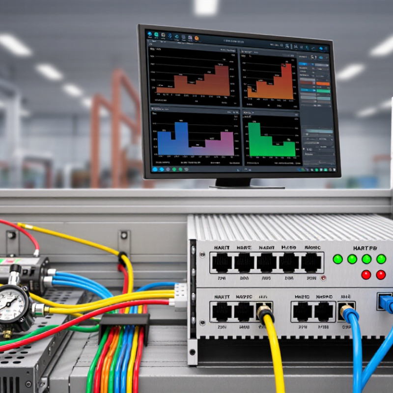
A HART Modbus TCP gateway is an industrial communication device that connects HART field instruments with Ethernet-based control systems. It translates information between two different protocols. HART usually travels over existing 4–20 mA wiring, while Modbus TCP operates through Ethernet networks.
In practice, the gateway communicates with connected HART instruments and reads process variables, device status, configuration data, and diagnostic information. It then places this information into Modbus TCP registers. A PLC, SCADA platform, or industrial computer can read those registers using standard Ethernet communication. The gateway may also send selected commands back to the instruments.
The process sounds simple.
However, careful mapping is essential. A temperature value, for example, must use the correct register, data type, unit, and scaling method. Engineers should also check HART addresses, polling intervals, communication errors, and instrument response times. Poor settings can create delayed readings or confusing values.
A practical installation often includes a gateway near the field wiring, an Ethernet connection to the control network, and software for register configuration. Network segmentation and access controls improve reliability and reduce unwanted communication. This is often overlooked.
The gateway does not magically repair weak wiring or incorrect instrument configuration. Signal quality, grounding, power availability, and cable length still matter. During commissioning, technicians should compare gateway values with local instrument readings and record any differences before placing the system into routine operation.
A HART Modbus TCP gateway polls field devices through the HART protocol, extracts process variables and diagnostic information, and maps the results to Modbus TCP registers for use by PLCs, SCADA systems, and industrial software.
The chart shows illustrative process values normalized to each device’s configured measurement span. HART commonly provides four dynamic variables—PV, SV, TV, and QV—which a gateway can expose through separate Modbus TCP registers. Actual values and register addresses depend on the connected field device and gateway configuration.
A HART Modbus TCP gateway connects field instruments with industrial Ethernet systems. It translates HART data into Modbus TCP registers for controllers, monitoring software, or maintenance stations. The gateway usually contains a HART modem, Ethernet interface, processor, memory, and isolation circuits. Each part has a practical role. The modem reads digital data from the 4–20 mA loop. The processor organizes variables, status information, and diagnostic codes. The Ethernet interface then publishes these values across the plant network.
Communication starts with a Modbus TCP client sending a request. The gateway checks the register map and contacts the selected HART device. It may retrieve process value, sensor status, device identification, or calibration details. Results return as structured registers. Polling speed depends on loop quality, device response time, and the number of connected instruments. A neat wiring diagram can still hide noise or poor grounding. That part is easy to underestimate. Clear addressing and carefully documented register mapping prevent many commissioning errors.
Tips: Confirm loop resistance and polarity before testing. Use shielded cable where electrical noise is present. Record every HART address beside its physical instrument tag. Test one channel before enabling wider polling. Leave spare register space for future diagnostics. One detail matters: gateway defaults may not match your control system.
| System Dimension | Key Component or Function | How It Works | Typical Data or Specification | Communication Direction |
|---|---|---|---|---|
| Gateway Purpose | Protocol conversion | The gateway reads HART field-device data and presents the information as Modbus TCP registers or status points for an Ethernet-based control or monitoring system. | HART field communication converted into Modbus TCP data objects | HART side to Ethernet side, with configuration commands usually supported in the reverse direction |
| Field Device Layer | HART-compatible transmitter or instrument | The device measures a process variable and communicates digital information over the same wiring used for the analog current signal. | Primary variable, device status, engineering units, range limits, tag, serial number, and diagnostic information | Device transmits responses; the gateway sends requests and commands |
| HART Physical Layer | Analog current loop with digital FSK signaling | Digital data is superimposed on the 4–20 mA loop using frequency-shift keying, allowing analog process transmission and digital communication to share the same pair of wires. | 1200 bit/s digital communication; two-tone FSK signaling; 4–20 mA analog process signal | Bidirectional half-duplex communication |
| HART Communication Engine | HART modem and protocol handler | The modem separates digital HART signals from the current loop, while the protocol handler creates requests, checks responses, and manages device addressing and timing. | Command messages, device addresses, response codes, byte counts, checksums, and communication status | Requests from the gateway and responses from field devices |
| Gateway Processing | Data mapping and buffering | The gateway interprets HART response fields, converts values into configured data types, and stores them in an internal map for Modbus TCP access. | Floating-point values, integers, bit fields, device status, quality flags, and diagnostic codes | Internal processing between the field and Ethernet interfaces |
| Ethernet Network Layer | Industrial Ethernet interface | The gateway uses an Ethernet connection to exchange Modbus TCP messages with a programmable controller, supervisory system, data logger, or engineering workstation. | TCP/IP communication; Modbus TCP normally uses server port 502 | Bidirectional over Ethernet |
| Modbus TCP Function | Modbus TCP server interface | The gateway responds to requests from a Modbus TCP client by returning mapped process values, status information, or diagnostic data. | Read coils, discrete inputs, input registers, and holding registers; writable areas may be provided for supported commands | Modbus client requests data; gateway returns data or accepts permitted writes |
| Polling and Update Cycle | Scheduled HART polling | Because HART communication is relatively slow, the gateway commonly polls configured devices in sequence and refreshes its data map at a defined interval. | Update time depends on device count, command selection, response delays, retries, and loop conditions | Gateway initiates field-side requests; Modbus clients read the latest buffered values |
| Addressing Mode | Point-to-point or multidrop operation | In point-to-point operation, the analog current carries the primary measurement. In multidrop operation, several devices share the loop and digital communication is used for measurements. | Point-to-point commonly uses a unique device address; multidrop devices use distinct addresses on the same loop | Gateway addresses individual HART devices and exposes their data through separate mapped areas |
| Configuration Function | Device setup and register mapping | An authorized user can configure network settings, HART scan parameters, device channels, polling commands, data formats, byte order, and Modbus register assignments. | IP address, subnet settings, HART address, command schedule, register offset, scaling, and data type | Configuration software or Modbus client to gateway; gateway to field device when commands are supported |
| Diagnostics and Reliability | Error handling and device health monitoring | The gateway records communication failures, invalid responses, timeouts, device status changes, and data quality conditions so the control system can distinguish valid values from stale or failed data. | Timeout indicators, retry counters, checksum errors, device status bytes, quality flags, and last-update timestamps | Diagnostics collected from the HART side and reported through the Modbus TCP side |
| Control-System Integration | PLC, SCADA, DCS, or monitoring application | The upper-level system treats the gateway as a Modbus TCP server and reads standardized register locations instead of directly handling HART signaling. | Process values, alarms, device identity, maintenance data, and diagnostic registers | Control or monitoring system acts as Modbus TCP client; gateway supplies mapped data |
A HART Modbus TCP gateway connects intelligent field instruments with modern Ethernet control systems.
It does not simply “translate” two protocols. It interprets signals, checks device responses, and organizes process data for a Modbus TCP client.
FieldComm Group reports more than 40 million HART-enabled devices installed worldwide. That scale explains why protocol conversion remains important in upgraded plants.
HART instruments usually carry a 4–20 mA measurement with a digital signal superimposed on the same wires.
The digital channel uses frequency-shift keying at 1,200 bits per second. The gateway demodulates this signal and extracts values such as pressure, temperature, device status, and diagnostic information.
It then maps each value into Modbus registers. A PLC or supervisory system reads those registers through Ethernet using Modbus TCP requests.
Configuration quality matters more than the box itself.
Engineers must define register addresses, data types, byte order, scaling, polling intervals, and alarm handling.
A pressure value of 6.25 bar can become an integer value of 625, using a scale factor of 0.01.
Incorrect scaling can create convincing but dangerous readings.
The gateway should also preserve communication status, not only process values.
The 2023 ARC Advisory Group analysis of industrial networking highlights continuing growth in Ethernet-based integration, yet legacy instruments still require careful handling.
In practice, mappings are rarely perfect.
Unused registers, delayed diagnostics, and undocumented device behavior can expose weaknesses during commissioning.
Testing every variable against a calibrated source remains necessary.
A HART Modbus TCP gateway connects field instruments using HART communication with industrial systems using Modbus TCP. It translates measured values, device status, and diagnostic information between both protocols. The gateway usually has a HART interface on one side and an Ethernet port on the other. Its role is practical: make older field data readable by modern control or monitoring software.
The data exchange begins when a Modbus TCP client sends a request to the gateway’s IP address. The request identifies a register or device channel. The gateway then checks its channel map and sends a HART command to the selected instrument. The instrument returns a process value, such as pressure, temperature, or flow. It may also return a status code or diagnostic message. The gateway converts this response into Modbus registers and sends a TCP reply. The client reads those registers and displays the result.
Timing matters here. A slow instrument can delay the response or create a timeout.
Tips: Confirm each device address and register mapping before commissioning. Keep Ethernet settings documented. Test one channel with a known reference value. Check the unit, decimal position, and status bits. A reading may look correct while using the wrong scale. This is an easy mistake. Leave room for troubleshooting, because real installations rarely behave perfectly. Review communication logs when values freeze, repeat, or appear unusually stable.
A HART Modbus TCP gateway connects smart field instruments with Ethernet-based control systems. It translates HART variables into Modbus TCP registers. Measurements can include pressure, temperature, status, and diagnostic alerts. The gateway usually polls devices through a HART interface, then publishes organized data across an industrial network. Configuration matters. Incorrect register mapping can create quiet, costly errors.
Common applications include process monitoring, tank management, energy tracking, and predictive maintenance. The International Energy Agency reported that industry used about 37% of global final energy in 2022. Better instrument visibility can help identify compressed-air losses, abnormal temperatures, or inefficient pumps.
The U.S. Department of Energy also reports that motor-driven systems represent roughly 70% of industrial electricity consumption. A gateway can support this work when field data reaches maintenance software quickly. It cannot repair a poorly calibrated sensor.
Selection should begin with protocol compatibility, channel capacity, isolation, and environmental ratings.
Check whether the unit supports multi-drop HART networks and the required Modbus TCP register structure. Cybersecurity features deserve equal attention, including access control, secure configuration, and event logging. Response time matters for alarms, but not every application needs millisecond performance.
The first pilot may reveal undocumented wiring or inconsistent device tags. That is normal, and it should influence the final design. A low purchase price can become expensive when commissioning takes weeks. Reliability records, technical documentation, and practical support are stronger indicators than a crowded feature list.
It connects HART field instruments with Ethernet-based control systems. It converts instrument data into Modbus TCP registers.
It can provide pressure, temperature, device status, identification, and diagnostic details. Some values may arrive late.
HART commonly uses digital communication over existing 4–20 mA wiring. The gateway extracts digital data and organizes it for Ethernet communication.
A PLC or monitoring computer reads mapped Modbus TCP registers. Each register needs a defined address, data type, and unit.
Incorrect scaling can turn 6.25 bar into a misleading value. For example, 625 may require a 0.01 scale factor.
Check loop resistance, polarity, grounding, cable condition, and instrument addresses. Test one channel first.
No. Signal quality, power, grounding, and cable length still affect communication. The gateway is not magic.
Compare gateway readings with local instrument readings and calibrated sources. Record differences before routine operation begins.
Use clear addressing, network segmentation, and suitable access controls. Reserve registers for future diagnostics.
Polling speed depends on device response time, loop quality, and instrument count. A neat wiring diagram can still hide electrical noise.
A Hart Modbus Tcp Gateway is a communication device that connects HART field instruments with Modbus TCP-based control, monitoring, and data management systems. It typically includes HART communication channels, a processing unit, Ethernet connectivity, configuration software, and memory for organizing device information. The gateway reads digital process values, status information, diagnostic data, and configuration parameters from HART instruments, then converts them into structured Modbus TCP registers that supervisory systems can access over an Ethernet network.
During data exchange, the gateway communicates with connected HART devices, interprets their responses, maps relevant information to predefined registers, and answers Modbus TCP requests from a controller or monitoring platform. This allows existing HART equipment to participate in modern networked automation systems without replacing every field device. Common applications include process monitoring, equipment diagnostics, remote maintenance, and gradual control-system upgrades. When selecting a gateway, users should consider channel capacity, supported HART features, response speed, network security, installation conditions, configuration flexibility, and compatibility with the intended Modbus TCP system.